
Navigation
Sidebar
private:writeups:plasmaimpedanceprobes
This is an old revision of the document!
Plasma Impedance Probes (PIPs)
What it does
Measures
- Plasma frequency [Blackwell2005]
- Electron density (by measuring plasma frequency) [Blackwell2005]
- Plasma potential
- Collision frequency
Methods
PIPs can be operated in a number of methods
- Actively driven RF sweeps [Blackwell2005]. Relate the peaks and zero intercepts of Re(Z) and Im(Z) to circuit models to get the plasma frequency.
- Plasma oscillation (excite a two stream instability) [Blackwell2005]. Drive weak beam of electrons into the plasma to excite a two stream instability. It's frequency is close to the plasma frequency. An FFT of passive PIP measurements reveals the frequency.
Advantages
- [Blackwell2005] An improvement over Langmuir probes because contamination of the probe has a larger impact on its measurements than on the PIP.
- Better resolution and accuracy than traditional Langmuir probes [citation]
Disadvantages
- More complicated. Requires careful setup/calibration and the use of an expensive network analyzer.
- (Check this) Cannot be used in real-time because the network analyzer data can only be post-processed.
Sources of error
- [Blackwell2005] recommends “choosing sufficiently shielded coax cables so that the impedance characteristics are not changed as cables are moved around during the experiment. ”
- [Blackwell2005] Nearby objects to the probe reflected radiation
- [Blackwell2005] At frequencies related to certain wavelengths, standing waves can form in the chamber.
Types of electrodes used
- Planar probes
- Spherical probes - leads to a simpler analysis [Blackwell2005]
- Monopole antenna [Bilen1999]
[Blackwell2005]
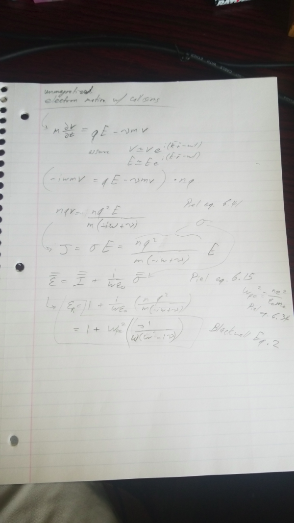
Blackwell2005 discusses a PIP in a cold (cold ions) and unmagnetized plasma using a spherical probes. Provides a derivation of the circuit model (I reproduce part of it below) that captures the impedance of the sheath and the plasma.
Derivation of Eq. 2. Also citing Piel2009.
Calibration
A calibration is common to remove the impedance of the non-plasma components (coax feedlines, network analyzer, etc).
- [Blackwell2005] does this by attaching a 50ohm load and then a short at the end of the feedline with the other end attached to a network analyzer. “the calibration consists of programming the analyzer to add phase shifts to the value of G to cancel out the phase shift from the cable.”
private/writeups/plasmaimpedanceprobes.1593699336.txt.gz · Last modified: 2020/07/02 14:15 by admin


