
Navigation
Sidebar
private:writeups:hallthrusters
This is an old revision of the document!
Table of Contents
Tiered understanding of Hall thrusters
Tier 1 - Simplest
All rockets (chemical, electrical) generate thrust by throwing out particles at high velocity out their rear. Electric propulsion systems, such as Hall thrusters, use electricity (instead of chemical combustion) to create thrust.
Tier 2 - Ionize, accelerate, and re-neutralize
All but the simplest EP systems operate by injecting neutral propellant and then
- ionize the propellant,
- creating electromagnetic fields to accelerate the ions, and
- re-neutralize the ions to ensure the spacecraft maintains a neutral charge and that the ions are not re-attracted to the spacecraft.
The difference in each EP is system is how they address these three points. For Hall effect thrusters (HETs):
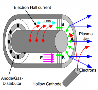
- Accelerate the positively charged ions with an axial electric field generated between an anode and cathode.
- Eject electrons into the fast moving cloud of ions to neutralize them before they get too far from the thruster.
- Rapidly rotate electrons azimuthally with an $ \frac{E_z \times B_r}{B_r^2}$ drift velocity. These fast moving electrons collide with and ionize neutrals.
This requires:
- Ions are ``unmagnetized“ and freely pass through the thruster.
- Electrons are ``magnetized” and are retained to ionize the neutrals and create the localized $E_z=-\nabla_z V$ to accelerate the freshly ionized ions. Because only electrons are rotating azimuthally, they constitute the Hall current.
Tier 3 - The 5 regions of the HET
HETs have effectively 5 regions (some of which overlap):
- (Injection/Conduction) The region near the anode where the neutral propellant is injected. Magnetic field is weak here. Any plasma here is very cold and this minimizes the potential drop across the anode's sheath. [Boeuf1998 for “Conduction” zone description]. In the conduction zone which extends on about 2 cm from the anode and corresponds to the low magnetic field region, the electron conductivity is large and the potential drop small. The ion production in this region is weak.
- (Ionization/Production) The ionization region where the Hall current ionizes the neutrals. Most
of the ions are created in the production zone located in the region where the magnetic field starts to increase, i.e., about 1 cm from the exhaust. The neutral atom density drops by a factor of 10 or more in the production zone. [Boeuf1998]
- (Acceleration) The Hall current also results in a large $E_z=-\nabla_z V$ that accelerates the ions. The acceleration region overlaps somewhat (TODO: define) with the ionization region. The positive ions are accelerated in the acceleration zone where most of the potential drops occurs, and which coincides with the large magnetic field region. [Boeuf1998]
- (Neutralization) Electrons from the cathode neutralize the high-velocity ion beam.
- (Exhaust) The high velocity beam of neutral gas provides thrust.
Where does the plume fit into this? Also, where exactly are the neutralization and exhaust regions?
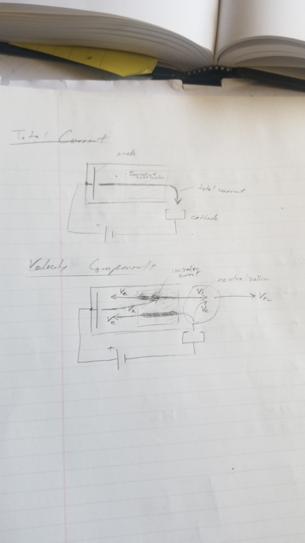
Two sources of current:
- Discharge power supply
- Ionization
The discharge current is the sum of the ion beam current $I_b$ and the counter streaming electron current $I_e$.
Three sources of ions and electrons:
- Cathode: provides mainly electrons (some ions) to 1) neutralize the ions and 2) get trapped and ionize neutrals
- Ionization: provides the majority of the ions that are accelerated and then neutralized for thrust. Electrons are collected by the anode
- Anode: (??? - read into this more)
Confined electron motion
Confined electrons in the thruster ionize propellant which leads to a strong localized axial electric field which then accelerates the recently ionized ions for thrust.
Three motions of confined electron flow (add details, equations, etc)
- Gyrorotation around $B_r$.
- Radial bounce motion due to $\nabla_r B_r$. Assisted by negative charge of ceramic insulator from sheath effects.
- Azimuthal $E \times B$ rotation (Hall current) which ionize the propellant.
Collisions - classic transport (add detail)
Anomalous transport (see below)
Cathode
Roles of the cathode (Hollow cathode or HC)
- Provide the axial electric field to accelerate the ions. The cathode generates the axial electric field between it and the cathode with the discharge power supply. The total voltage difference is the ``discharge voltage“.
- Provide electrons to neutralize the high velocity ion beam and also initialize and sustain the neutral ionization. The cathode creates electrons both through thermionic emission and through ionization of a small amount of propellant (neutral gas) flowed through the HC.
Electron transport
Neglecting collisions
Neglecting collisions, trapped electrons have three motions.
- Gryo-motion around $B_r$
- Radial bounce motion causes by A) a $-\nabla_r B_r$ magnetic mirror effect as well as B) the negative charging of the insulators
- Azimuthal $E_z \times B_r$ rotation.
TODO - Create an idealized version of Fig. 8 in [Boeuf2017] to highlight (and maybe exaggerate) the three motions.
Axial Transport with collisions
[Hoer2004] To optimize the efficiency of a Hall thruster it is critical to minimize the axial electron current by controlling the strength and shape of the magnetic field.
Classical transport
Classical (collisional) diffusion does not account for the observed electron current as the measured values are too large. This difference in diffusion is termed, “anomalous transport”.
[Boeuf2017] - has a good derivation. Maybe use it instead of Hofer's below.
[Hofer2004] - Derivation below
One dimensional steady-state electron motion is
$\nu_e n_e v_{ez} m_e + e n_e E_z + j_{e\theta}B_r + \nabla_z p_e = 0 $.
Including the relationship $\Omega_e = \frac{j_{e\theta}}{j_{ez}}$, the axial current can be solved
$j_{ez} = \mu_{ez} \left( -e n_e E_z - \nabla_z p_e \right)$
where
$\mu_{ez} = \frac{e}{\nu_e m_e} \left( \frac{1}{1+\Omega_e^2} \right) $
and the axial electric field ($E_z$) and pressure gradient ($\nabla_z p_e$) are the driving terms for the electron motion (current).
In regions where electrons are strongly magnetized, $\mu_{ez}$ simplifies to
$\mu_{ez} \approx \frac{e}{\nu_e m_e \Omega_e^2} = \frac{\nu_e m_e}{e Br^2}$
Anomalous transport
Classical collision frequency is around $10^6$ to $10^7$ $s^{-1}$ whereas measured effective collision frequencies is $10^7$ to $10^8$ $s^{-1}$, about an order of magnitude larger. This difference is termed “anomalous transport”. [Hofer2004]
Mechanisms responsible
The mechanisms responsible are likely from two sources : [Hofer2004]
- Turbulence related to azimuthal plasma oscillations and
- near-wall effects (collisions, near-wall conductivity, etc)
Both mechanisms each play a role in different regions of the discharge chamber and at different thruster operating conditions. Mathematically, this can be accounted by including all three contributions (classical e-n collisions, wall interactions, and turbulence).
$\nu_e = \nu_{en} + \nu_{wall} + \nu_{turb}$.
Regions
- Closed-drift region - classical collisions along agrees with results
- Downstream near the anode and exit plane - Bohm diffusion is needed
- ___? - Near-wall interactions become important (TODO)
Classical collisions
$\nu_{ne}$ typically dominates $\nu_{ee}$ and $\nu_{ie}$, and therefore the two are typically ignored.
Turbulence contribution
- [Bohm1949] - Bohm mobility model of electrons - able to explain large cross-fieldd electron currents observed in fluctuating plasma environments. Foundation of models for $\nu_{turb}$.
- [Stangeby2000 and Lobbia2010] - Simple model for cross-field flux due to turbulence and azimuthal oscillations. $\Gamma_z = \frac{1}{B_r} \left < \widetilde{n}_e \widetilde{E}_\theta \right > = \frac{| \widetilde {n}_e| |\widetilde {E}_\theta|}{B_r} cos \left( \delta_{ne} + \delta_{E\theta} \right ) = \frac{| \widetilde {n}_e| |\widetilde {E}_\theta|}{B_r} \left( 1- sin^2 \left( \frac{ \delta_{ne} + \delta_{E\theta}}{2} \right ) \right )$
- [Janes/Lowder????] - Azimuthal fluctuations in E and density gradients create an adiabatic ExB drift and could result in anomalous diffusion. Agrees closely with Bohm-like mobility.
- Might be more prominent with lower voltages and lower temperature electrons.
Near wall contributions
- [Morosov????] First introduced “near-wall conductivity” to model wall-electron collisions. The wall effectively acts as a stationary macro-particle. Allows for electron reflection and secondary electron emission.
Scaling laws
Electrons are magnetized
- Electron gyroradius is smaller than channel dimension, $r_e = \frac{m_e}{eB} \sqrt{\frac{8 k T_e}{\pi m}} \ll L$
- Electro gyrofrequency is larger than the collision frequency, $ \Omega_{max} \gg \frac{\omega_{gyro}}{\nu} \gg 1 $ where $\Omega_e = \frac{\omega_{gyro}}{\nu}$ is the Hall parameter. Too low a hall parameter, the electrons are no longer confined (trapped). Too high a hall parameter, too few collisions with neutrals result in too few ions. [Hofer2004] The high value of the electron Hall parameter, being much greater than unity but not infinite, means that electrons undergo enough ionizing collisions on their way to the anode to sustain the plasma discharge while still maintaining a bulk azimuthal current that is several times larger than the axial current. Therefore, it is reasonable to expect that efficient Hall thruster operation can only be realized over a limited range of electron Hall parameters and that there must be an optimum magnetic field strength. This has been confirmed by experiments, which have shown that the electron Hall parameter attains a value of several hundred in the closed-drift region.
- [Hofer2004] The electron hall parameter, $\Omega_e$, is related to the axial and azimuthal (Hall) current densities with the equation $\Omega_e = \frac{j_{e\theta}}{j_{ez}}$.
Ions are unmagnetized
- Ion gyroradius is larger than channel dimension, $r_i = \frac{m_i}{eB} \sqrt{\frac{2 e V_{bias}}{m_i}} \gg L$ (assuming cold ions accelerated by axial electric field)
Rapid ionization
- Ions must be fully ionized to achieve high efficiency. Therefore, their mean free path must be shorter than the plasma length. Also, you want the ions to ionize as fast as possible such that they are accelerated through the entire acceleration region. $ \frac{\lambda_i}{L} = \frac{\frac{v_n}{n_e \left < \sigma_i v_e \right >}} {\frac{v_nV_d w}{I_{Hall} \left< \sigma_i v_e\right> B}} = \frac{I_{Hall} B}{n_e V_d w} \ll 1 $.
Advantages/Disadvantages
Advantages
- Higher thrust/weight than most EP
- Fewer power supplies than ion thrusters
- Current density is limited by material and thermal limitations (and not space-charge like Ion thrusters)
- Lower part count
- Less stringent voltage isolation requirements (citation?)
Disadvantages
- Lower specific impulse than most EP
- Acceleration region and ionization region overlap
- Efficiency and lifetime are usually lower when compared to Ion thrusters
Efficiencies
- Total efficiency, thrust times exhaust velocity divided by electrical input power, $\eta_T=\frac{T v_{exhaust}}{P_{in}}$
- Cathode efficiency. Since most of the cathode mass flow is “not used” for its momentum, only the anode mass flow is relevant.
- Electrical utilization efficiency. How much power goes into the discharge (current times voltage) instead of auxiliary systems plus the discharge.
- The beam voltage and is a (large) fraction of the total discharge voltage. This is due sheath effects, the coupling voltage, etc.
- Analyzed at the exit plane, the ion beam current is the only current that results in thrust. The other current (the backstreaming electrons from cathode to anode) do not directly contribute to thrust. [Hofer2004] The current utilization efficiency, $\eta_b = \frac{I_b}{I_d} = \frac{1}{1+ \left( \frac{I_e}{I_b} \right)}$ where $I_b$ is the ion beam current, $I_e$ is the counter streaming electron current, and $I_d = I_e + I_b$ is the discharge current. The current utilization efficiency is maximized when the electrons are 100% trapped (axially stationary).
- Beam divergence (gamma squared term)
- Multiply charged ions (also in the gamma squared term)
Instabilities
Several common low-frequency instabilities in HETs
- these oscillations can indeed lead to violent conditions that could potentially damage the thruster discharge supply
- these oscillations may “provide the necessary electric conductivity for operation [and] this type of oscillation can be considered as useful or normal.” - Zhurin, V., Kahn, J., Kaufman, H., Kozubsky, K., and Day, M.,”Dynamic Characteristics of Closed Drift Thrusters,“ IEPC-93-095, 23rd International Electric Propulsion Conference, Seattle, WA, 1993.
Sources:
- [Boeuf2017] has a brief recap
- [Choueri2001] has a thorough review but is a little dated
1. Breathing mode - Axial (m=0) ionization instability
[Choueiri2001]
- Typically 1 to 20 kHz
- Called a “breathing mode”
- Caused by a periodic depletion and replenishment of the neutral near the HET exit.
- Since the magnetic field in that region is large, the associated low electron conductivity leads to an increase in the electric field required to maintain current continuity. The resulting enhanced ionization depletes the neutral density causing the downstream front of the neutral flow to move upstream into a region where the ionization rate is lower. This decrease in upstream ionization rate will cause a decrease in the flux of electrons to the exit which causes the ionization there to abate and effectively brings back downstream the neutral gas front.
- Strong function of $\frac{B_r}{B_{r,optimal}}$. This (and honestly most) instabilities are avoided by changing a different parameter space, i.e. B/Bopt.
- Sensitive to correctly designed PPU and matching filter to suppress this mode.
[Boeuf2017]
- 10-20 kHz range
- “Reasonably well understood”
- Due to strong ionization of the atom flow in the large magnetic field region, the neutral atom front moves upstream in a lower magnetic field region where ionization becomes less efficient because the electron mobility is larger. This leads to a decrease of the current till the neutral atom front moves back to the exhaust region where intense ionization can take place again. This oscillation mode has been termed as “breathing mode”
- Period of oscillation is related to the time necessary for neutrals to replenish the ionization region.
- Can be modeled (with many simplifications) as a predator-prey system of neutrals and ions. The result is a harmonic oscillator. TODO - Find derivation and put here.
[Fife1997]
- Provides simple model of the mode
2. Spoke mode - Azimuthal (m>0) ioniziation instability
[Choueiri2001]
- Typically 5 to 25 kHz
- Ionization instability. A coupling between the density nonuniformities and the ionization process. The spoke can thus be thought of as resulting from incomplete ionization of the gas and rapid loss of newly born ions.
- Always anchored to the anode. May extend down the discharge chamber is some situations.
- Has a 15 to 25 degree azimuthal tilt down the discharge chamber.
- Oscillating azimuthal electric field creates a $ v_z=$ $\frac{E_\theta \times B_r }{B_r^2}$ $=\frac{E_\theta}{B_r}$ axial drift velocity that is part of the ``anomalous transport” mechanism that causes electrons to more rapidly escape confinement.
- Claims the detailed physics describing this instability are poorly explored. (Is this still correct?)
[Me]
- Maybe another way to think of this is an azimuthally rotating ionization region with an azimuthal structure $exp \left( i(m\theta - \omega t) \right) $ where the mode number, $m$, is an integer greater than 0.
3. Azimuthal drift instability related to axial gradients in $\nabla_z B_r$
[Choueiri2001]
- Typically 20 to 60 kHz
- Azimuthal propagations
- Not related to ionization instabilities
- Related to the gradient of the radial electric field along the z-axis.
- Classified as a drift instability associated with the $\nabla_z B_r$ drift velocity
- Related to “fast magnetosonic waves”
[Hofer2004]
- For the purpose of stability, $\nabla_z B_r$ is designed to be positive along the discharge chamber, with the minimum magnetic field at the anode and maximum near the exit plane.
4. Poorly understood ...
[Choueiri2001]
- Typically 20 to 100 kHz
- Non-azimuthal
- Poorly reported in literature, partially because of the overlap with the previous azimuthal instabilities.
- Thought to be related to 1) neutral collisions or 2) ionization.
5. Axial "Transient-time" oscillations
[Choueiri2001]
- Typically 70 to 500 kHz
- Instability has a strong scaling with $k_z u_i$ (the axial ion transport transience) and is therefore referred to as the “transient-time” instability or oscillation.
- Quasiaxial electrostatic waves
- Tend to be relatively turbulent
- Presumed to play an important role in plasma transport (anomalous transport)
- Well predicted by linear theory of gradient driven magnetosonic waves with a primarily axial propagation
- Due to the coupling of the “beam mode” ($k_z u_i$) with $\nabla_z B_r$ driven oscillations.
6. high frequency azimuthal drift waves
[Choueiri2001]
- Typically 0.5 to 5 MHz
- Azimuthal propagation
- Not well documented (modes at this frequency and higher are typically ignored in favor of lower frequencies)
- Related to the electron drift velocity
Etc. (there are lessor or newly discovered instabilities)
TODO
Performance models
Thruster performance
[Hofer2004] Thruster performance is determined by the efficiency of the ionization and acceleration processes and is typically subdivided into three distinct processes:
- the fraction of ion current contained in the discharge current, that is, the current utilization efficiency,
- the conversion of mass flow rate into ion current, that is, the mass utilization efficiency, and
- the conversion of voltage into axially directed ion velocity, that is, the voltage utilization efficiency
Hofer then goes on to describe a forth, the charge utilization efficiency.
1. Current utilization efficiency
The net current flow is composed of ion (or beam) current to provide thrust and electron current that ionizes the propellant. The total discharge current is
$I_d = I_i + I_e. $
Ideally, you want to completely ionize the propellant with as little electron current as possible so that the ions (which have all the momentum and therefore provide the thrust) constitute the vast majority of the current. The (ion) current utilization efficiency is
$\eta_{beam} \equiv \frac{I_i}{I_e} $
As a practical matter, this efficiency will never reach 100% because some electron current is always needed.
2. Mass utilization (ionization) efficiency
The total mass flow from the anode consists of both ions and neutrals.
$\dot{m}_{anode} = \dot{m}_{i}+\dot{m}_{n} $
Ideally, the neutral propellant is 100% ionized. The mass-ionization efficiency is therefore
$ \eta_{mass-ionization} = \frac{\dot{m}_i}{\dot{m}_{anode}}$
and the true (density) ionization efficiency is $ \eta_{ionization} = \frac{n_i}{n_i + n_n}$
Note that they key distinction between the two is the velocity difference. Neutral particles have an average velocity around 0.4 km/s, and ions have an average velocity around 20 km/s.
Acceleration efficiency
Ideally, ions are accelerated over the full potential drop of the discharge voltage and are done so with no loss. However, this is completely true.
- Sheath effects at the anode (and I think a similar effect at the cathode) causes a localized voltage drop that does not accelerate ions.
- The ionization and acceleration regions overlap. Meaning a neutral may be ionized at different axial locations and therefore have more or less of a voltage drop for acceleration.
- Ionization potential of the propellant is lost energy.
- Wall interactions.
- Multi-ionized ions.
- Radial beam divergence
- Plasma oscillations
- etc.
Early definitions
Thrust, from the POV of the thruster, is
$T = \frac{\partial}{\partial t} (m v) = \dot{m} v + m \dot{v}$
From the frame of reference on the thruster in steady-state operation, the thruster is not moving, the propellant has a constant mass flow rate $\dot{m}$ and a constant exhaust velocity $v$ when it leaves the thruster. Therefore, this equation reduces to
$T = \dot{m}_{prop} v_{exh}$
The total mass flow is split between
The cathode (mass) efficiency is defined as
$ \eta_c = \frac{\dot{m}_a}{\dot{m}_t} = \frac{1}{1+\frac{\dot{m}_c}{\dot{m}_a}} $
where the total mass flow is split between the anode $\dot{m}_a$ and the cathode $\dot{m}_c$ (the majority leaves at the anode).
$\dot{m}_{total}=\dot{m}_a+\dot{m}_c$
The total mass flow rate can then be expressed as
$\dot{m}_t = \dot{m}_a+\dot{m}_c = \frac{\dot{m}_a}{\eta_c}$
From the thrust equation earlier, the total effective exit velocity is
$c_t = \frac{T}{\dot{m}_t} = \frac{T}{\dot{m}_a}\eta_c$
Therefore, the total power of in the exhaust (jet) is
$P_{jet} = \frac{1}{2} T c_t $
However, this isn't particularly useful as we cannot measure $c_t$ an
Total thrust efficiency
The total thrust efficiency is the ratio of the kinetic power of the exhaust (which provides thrust) to the total electrical power input (i.e. how much “push” do we get per unit of energy input).
$ \eta_t = \frac{P_jet}{P_t} = \frac{\frac{1}{2} T c_t}{P_t} $
$ \frac{\frac{1}{2}T c_t }{P_t} = \ldots = \frac{T^2}{2 \dot{m}_a P_d} \eta_c \eta_{mag}$
And the total specific impulse is defined as
$I_{sp} \equiv \frac{T}{\dot{m}_t g} = \frac{T}{\dot{m}_a g}\eta_c = \frac{c_t}{g}$
Total power efficiency
Total power is the sum of the power to plasma discharge $P_d$, the magnetic field $P_{mag}$, and other auxiliary devices $P_{aux}$ such as the cathode keeper. $P_{aux}$ is typically zero in modern HETs.
$P_{tot} \approx P_{d} + P_{mag}$. $P_{mag}$ is typically 1% but can be as much as 4% depending on the design.
Electromagnetic efficiency is defined as
$\eta_{mag} \equiv \frac{P_d}{P_t} = \frac{1}{1 + \frac{P_{mag}}{P_d}}$
Magnetic field design
- [Hofer2014] While a complete understanding of electron dynamics is currently unavailable, it is known that the electron dynamics can be influenced by controlling the shape and strength of the magnetic field. At least in this sense, it is fair to say that the magnetic field is the most important aspect
of Hall thruster design.
Open issues related to HETs
(Need citations…)
- Anomalous transport
- Plasma plume/exhaust interaction with spacecraft
- Improving ground based models/experiments to successfully predict space operation
- etc
Probes and other diagnostics
The goal of this section is to list common (or even uncommon) diagnostics associated with measuring “anything” in a Hall thruster.
- Laser Induced Fluorescence (LIF) - Measures ion and atom (presumably neutral?) mean velocity. [Boeuf2017]. Used to study instabilities (need specifics) [Boeuf2017].
- Langmuir probes - temperature, density, plasma potential
- Segmented electrodes - Used to study instabilities (need specifics) [Boeuf2017].
- “Fast imaging probes” - Used to study instabilities (need specifics) [Boeuf2017]. I don't know what this probe actually is.
- Discharge current measurements - Measurement of total current, I_elec + I_ion. Also used to study instabilities (as instabilities causes oscillations in conductivity).
- Highspeed videos of exhaust. Image is on-axis. - Used to study spoke instabilities.
Questions
- Why is there no ion saturation limit to Hall thrusters? Is this because of the “Double Layer” that forms as the effective cathode? And if so, I don't really understand this…
- Related, I don't understand how the HET exhaust is an “electrodeless” plasma…
- Coupling voltage? “the voltage required to extract current from the hollow cathode” WHY???
- Why is the floating common potential between the beam and cathode potentials?
- Why does the HC need to emit gas at all? Isn't thermionic emission sufficient to produce electrons?
- Choueiri2001 claims the physics of the spoke mode instability is largely unexplored (as of 2001). Is this still true?
- Where is the neutralization region in the context of the HET, ionization, and acceleration regions?
- I've seen mixed comments as to whether “axial electron transport” is all bad or whether “there are cases where electron transport actually improve”. Thoughts?
- [Boeuf2017] As the thruster size and power change, the current density does not change and stays on the order of 1000 A/m^2 in most Hall thrusters. Why?
- Would secondary electrons generated by electron striking channel walls be an alternative source of electrons?
private/writeups/hallthrusters.1596725691.txt.gz · Last modified: 2020/08/06 14:54 by admin


